

Astrology
Understanding the Impact of Retrograde Motion on Astrology Readings
Retrograde motion is one of the most talked about phenomena in astrology. When you see…

Observations
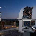
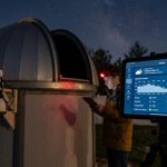
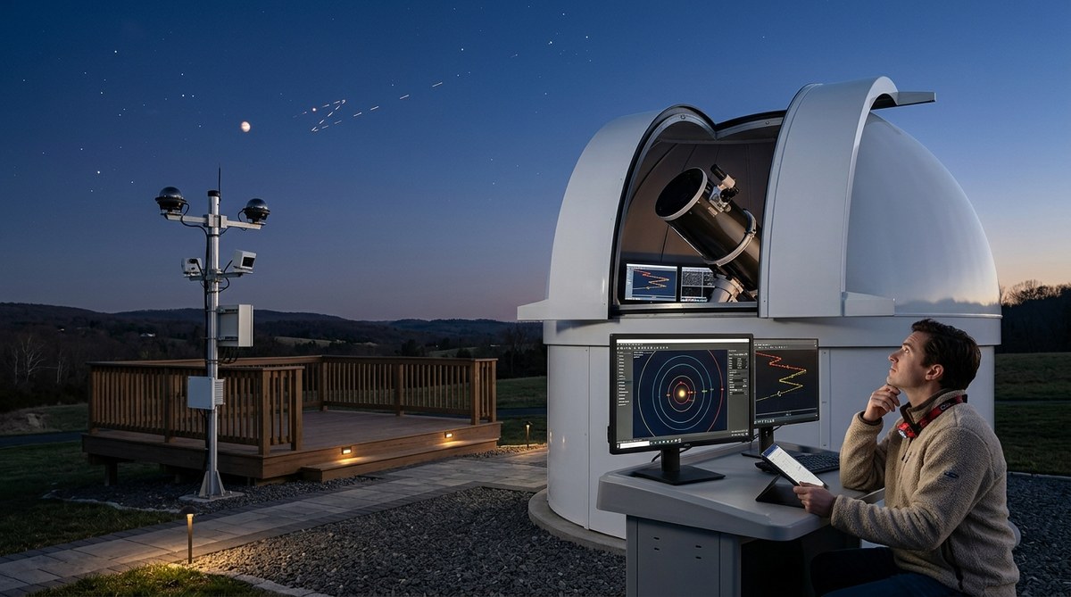
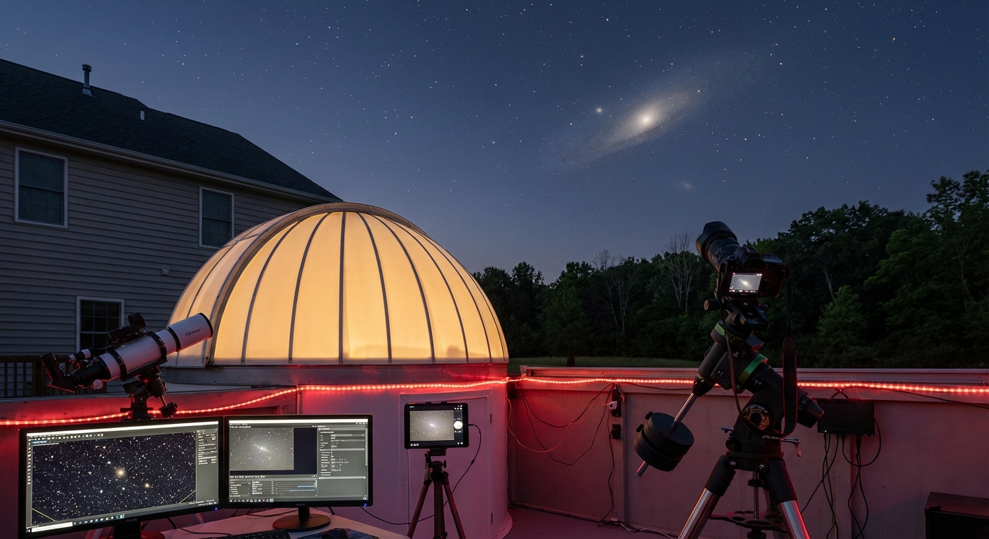
Discover How to Interpret Celestial Events Using Remote Observatory Data
Interpreting celestial events can seem complex, especially when you're relying on remote observatory data. Yet,…
Resource
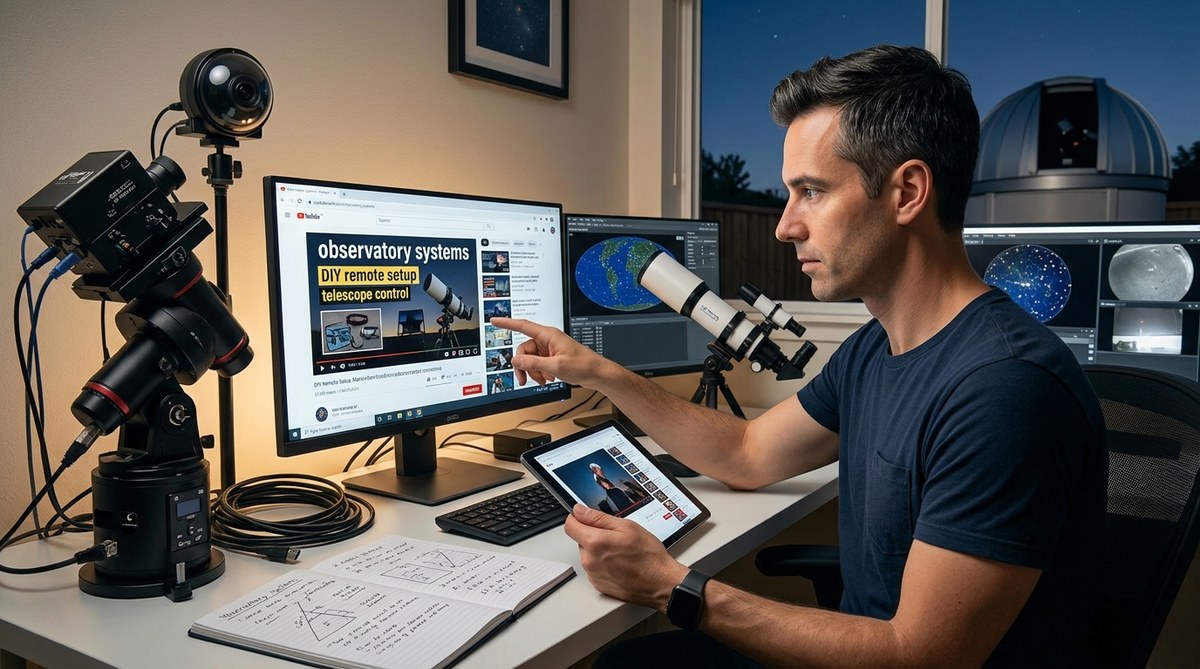
Educational YouTube Channels That Actually Help You Build Better Observatory Systems
Building and maintaining a quality observatory system can seem complex, especially for those new to…
Resource
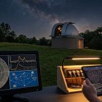
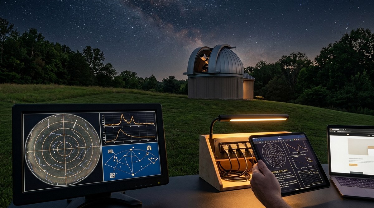
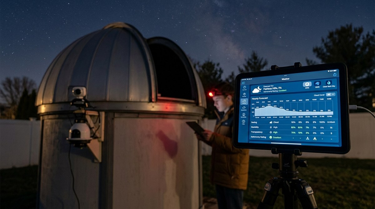
Where to Find Reliable Weather Data for Astronomy Observation Planning
Planning an astronomy session hinges on more than just knowing the night sky. It requires…
Guides & Tutorials
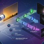
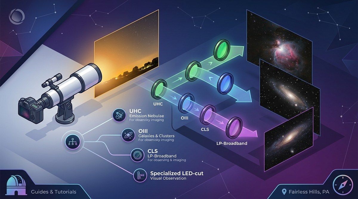
What Light Pollution Filter Should You Actually Use? A Decision Framework
Amateur astrophotographers and stargazing enthusiasts often face a common challenge: how to capture clear images…
DIY Projects
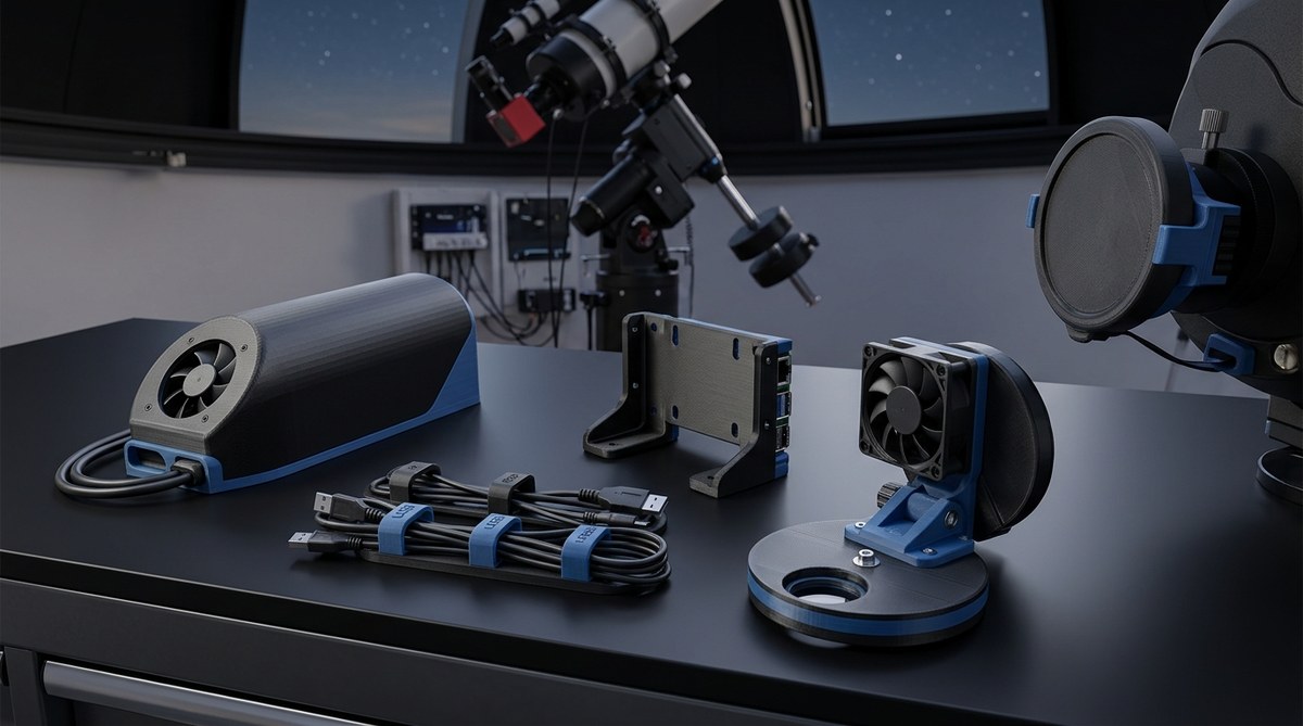
5 Essential 3D-Printed Accessories Every Remote Observatory Needs
Stargazing from a remote observatory offers unmatched clarity and detail. But setting up and maintaining…
DIY Projects
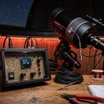
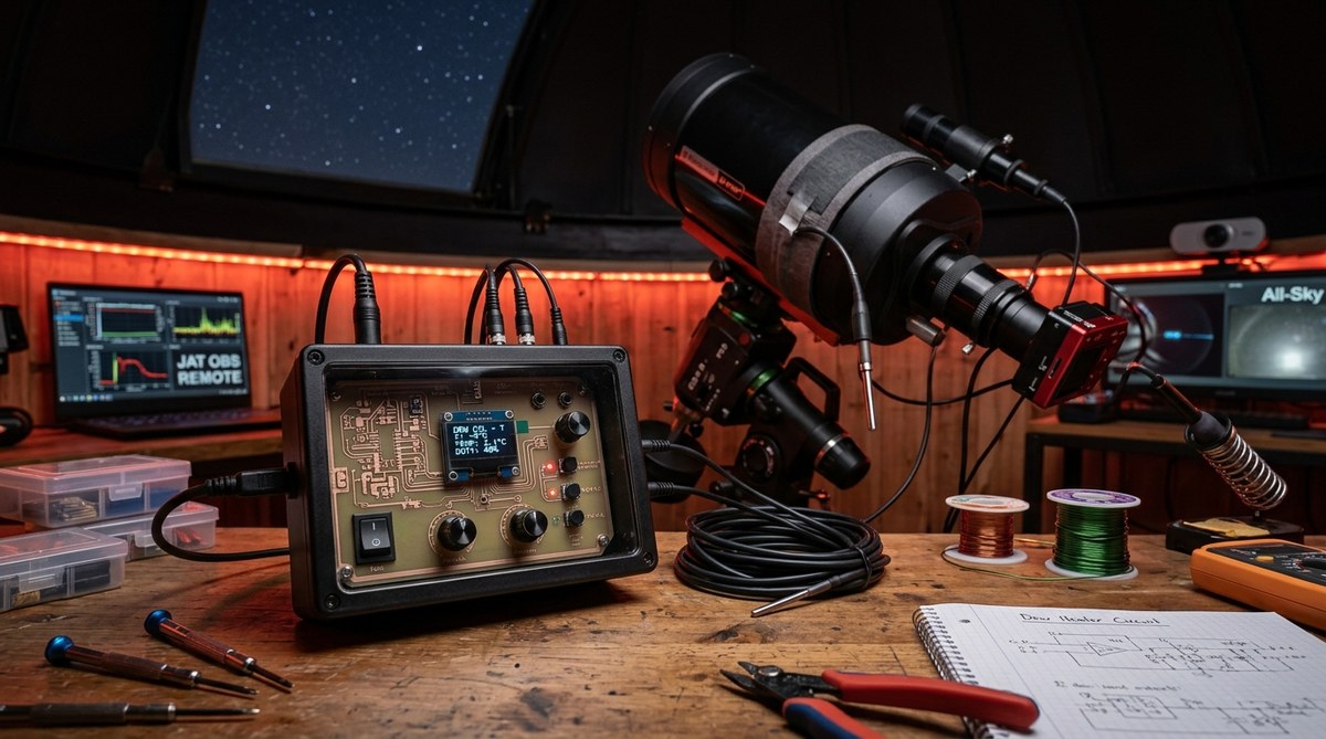
Building a Dew Heater Controller That Actually Works
Getting rid of dew on your telescope or camera lens is a common challenge for…
Software & Automation
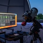
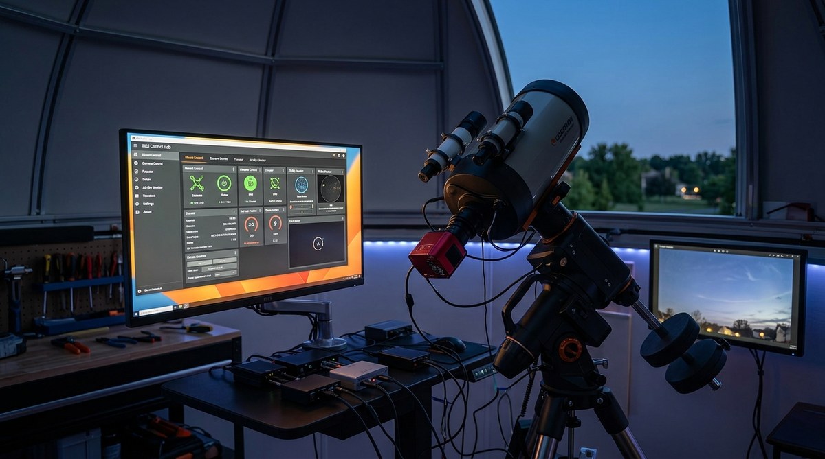
Can INDI Drivers Really Replace Proprietary Telescope Software?
Thinking about streamlining your astronomical setup? Many amateur astronomers and astrophotographers are discovering that INDI…
Astrology
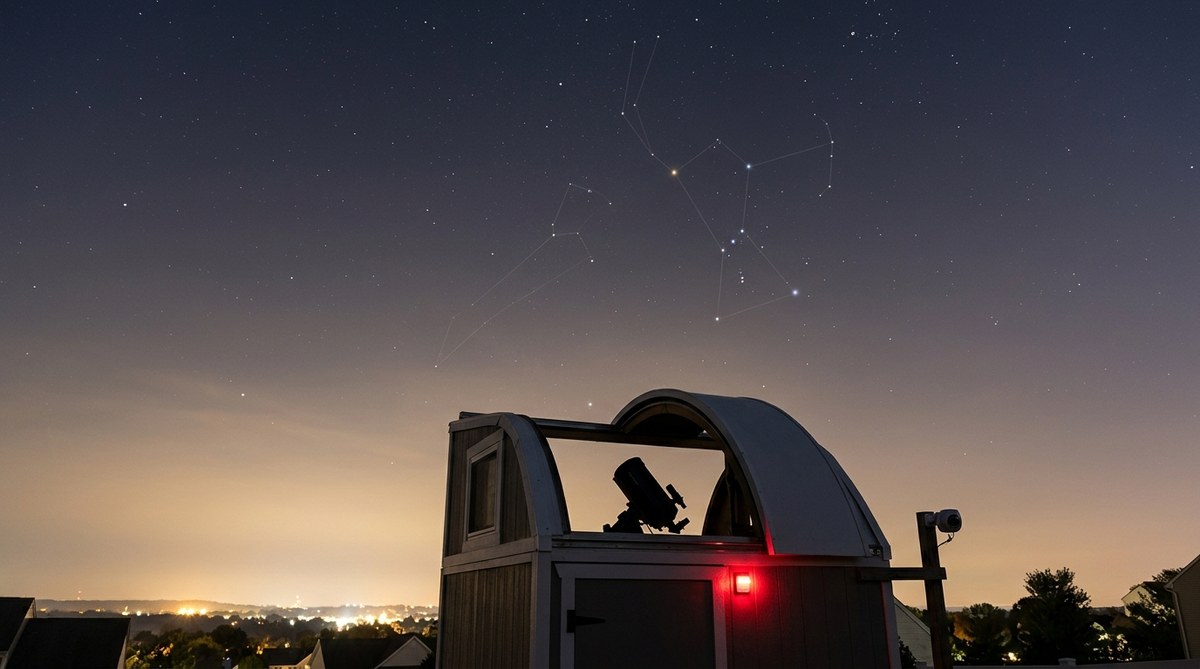
Can You Photograph Zodiac Constellations From a Light-Polluted Suburban Observatory?
Getting clear shots of zodiac constellations from a suburban backyard or areas affected by light…
Observations
Tracking Satellite Passes: Our Best ISS and Starlink Observations Explained
Tracking satellite passes offers a fascinating way to connect with space from your backyard. Whether…