Observations
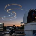
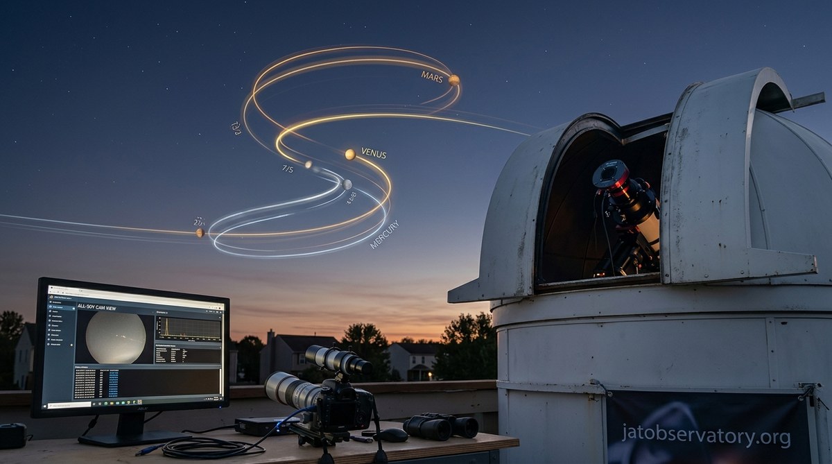
Three Planetary Retrogrades Captured by Our Observatory That Will Reshape Your Astrological Outlook
You know that moment when Mercury goes retrograde and your phone dies, an ex texts…

Software & Automation
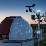
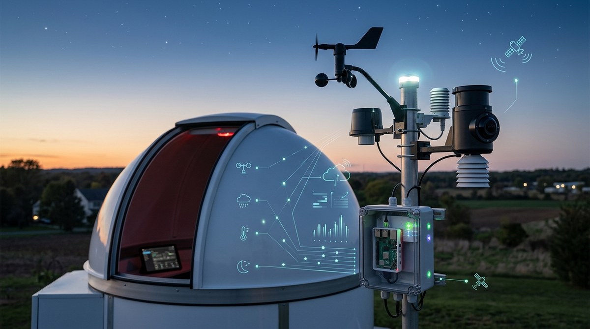
5 Ways to Automate Your Observatory’s Weather Monitoring in 2026
You step outside, look up at a perfectly clear sky, and rush to open the…
Equipment & Setup
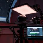
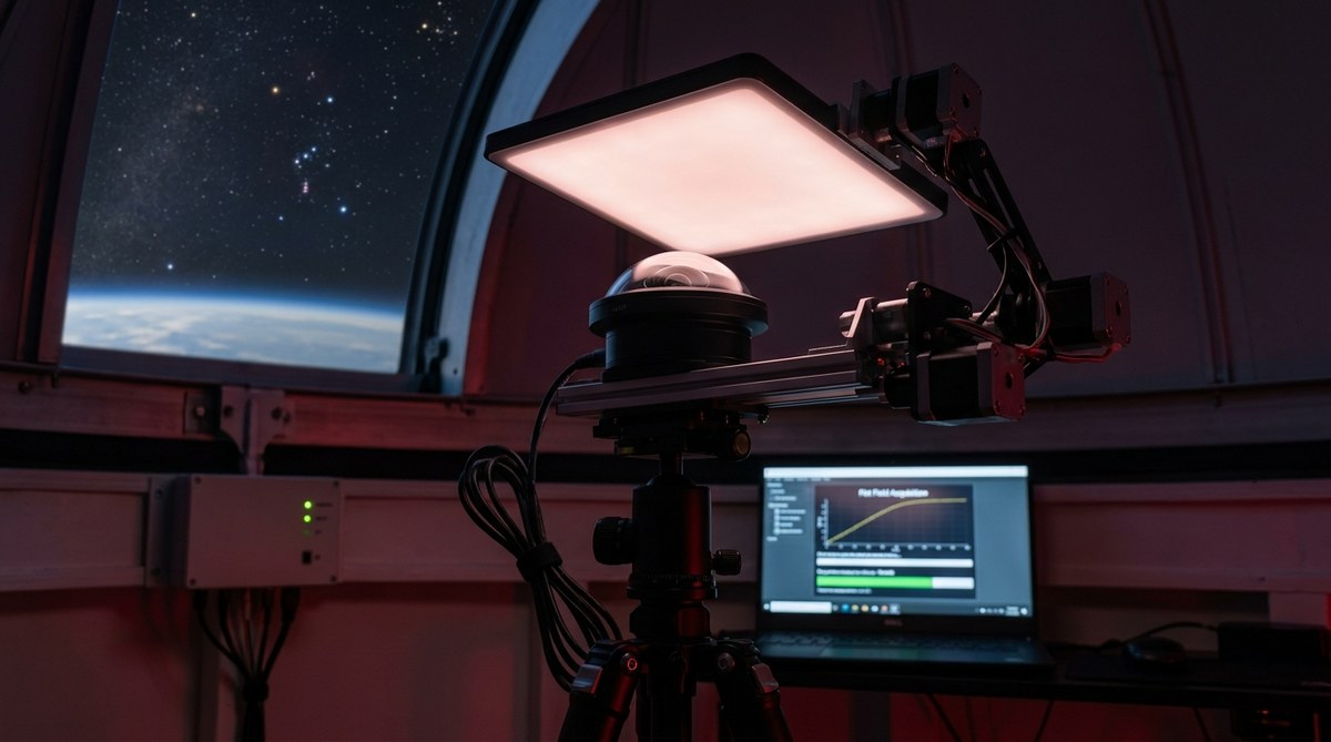
How to Automate Flat Field Calibration for Your All-Sky Camera
If you run an all-sky camera for night sky monitoring, you know the frustration of…
Equipment & Setup
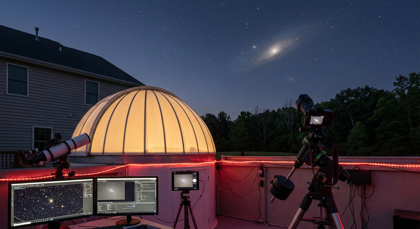
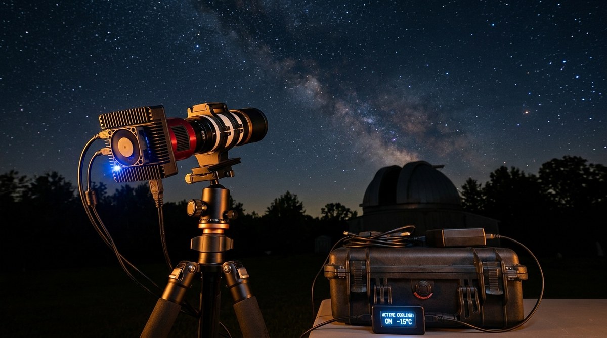
Why Your Remote Camera Needs Active Cooling for Better Night Sky Views
You finally get a clear night. Your remote camera is set up in the backyard.…
Astrology
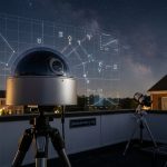
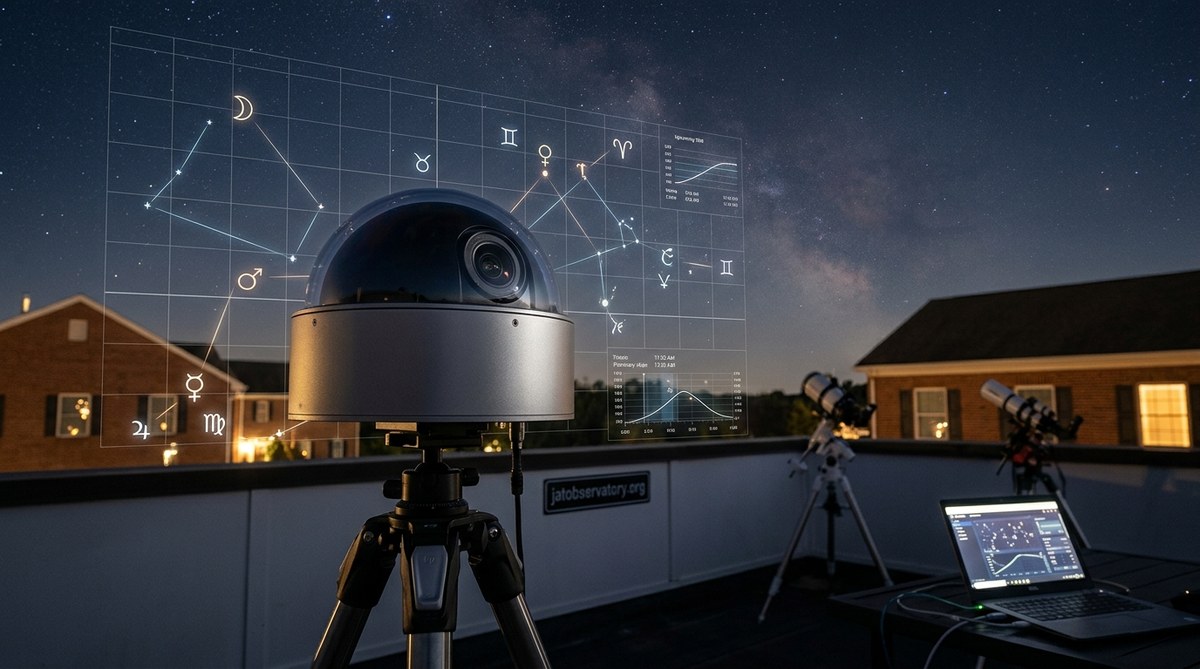
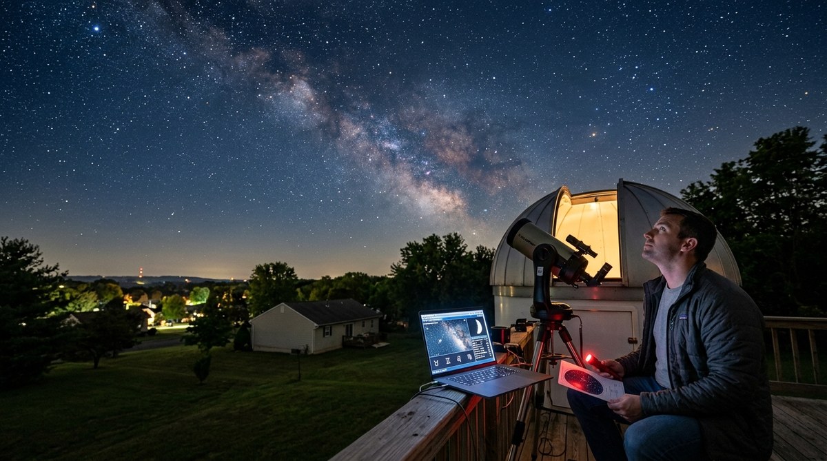
How to Use Your All-Sky Camera to Track Astrological Transits
You spent weeks building your all-sky camera. You dialed in the focus, weatherproofed the enclosure,…
Observations
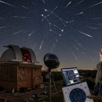
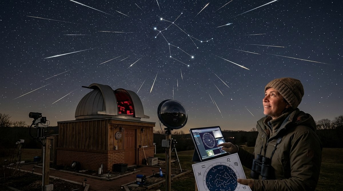
Why the 2026 Geminid Meteor Shower Is a Must-See for Astrology Lovers
The Geminid meteor shower returns every December, and 2026 is setting up to be a…
Equipment & Setup
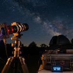
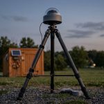
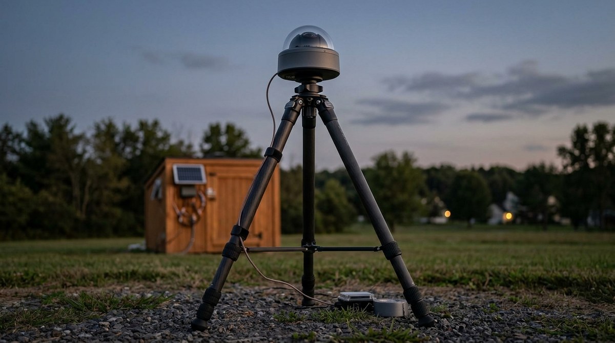
What’s the Best Tripod for Your All-Sky Camera? A Guide to Stability and Portability
You have spent weeks dialing in your all-sky camera. The focus is perfect. The gain…
Astrology
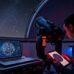
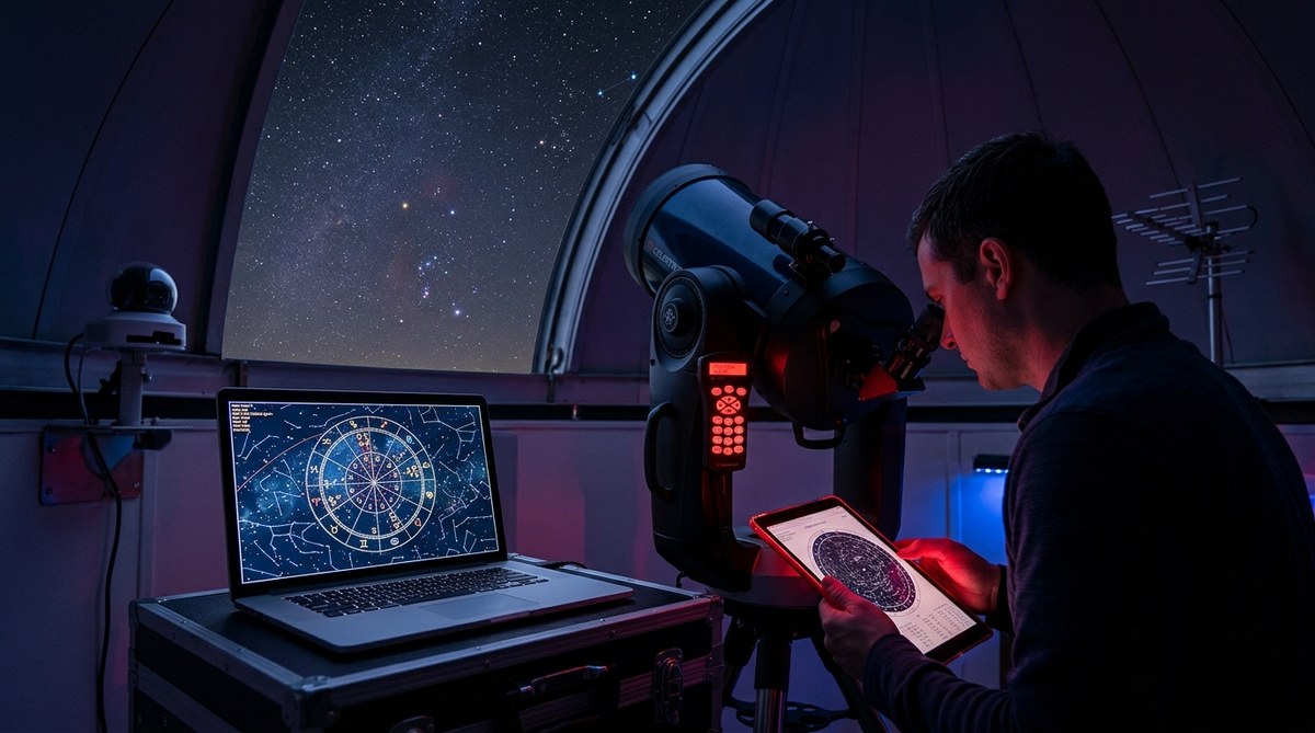
Mapping Your Birth Chart to the Night Sky: A Practical Telescope Guide
Your birth chart is a map of the sky at the exact moment you took…
Astrology
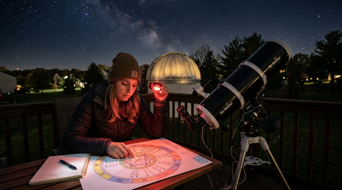
Decoding Astrological Birth Charts with Backyard Telescopes
Thinking about merging your love for stargazing with your curiosity about astrology? Using backyard telescopes…
Observations
Exploring the Connection Between Astrology Events and Recent Sky Observations from Fairless Hills
In the quiet neighborhoods of Fairless Hills, sky watchers have noticed a series of intriguing…