

Observations
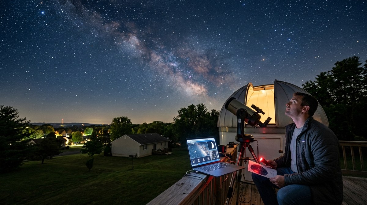
Exploring the Connection Between Astrology Events and Recent Sky Observations from Fairless Hills
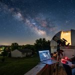
In the quiet neighborhoods of Fairless Hills, sky watchers have noticed a series of intriguing…

Observations
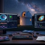
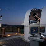
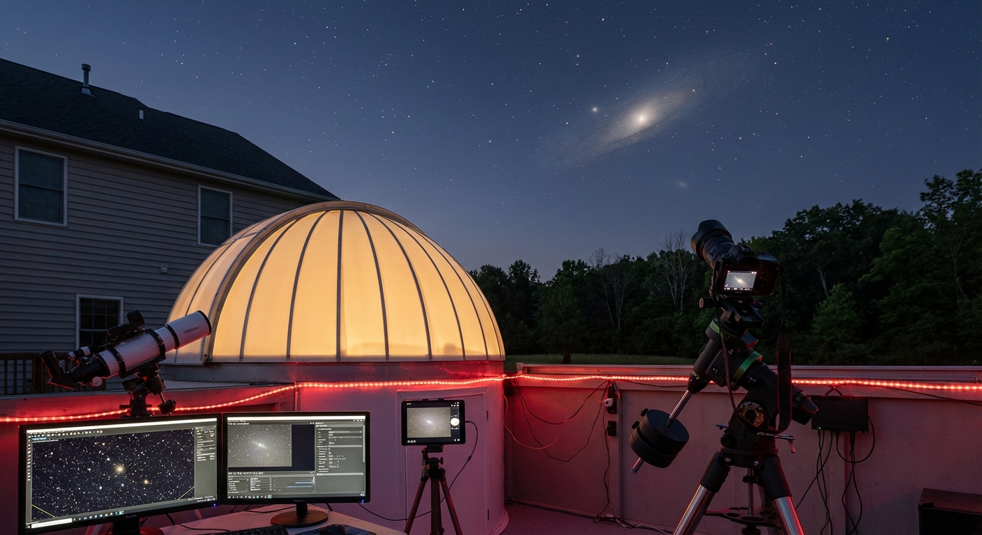
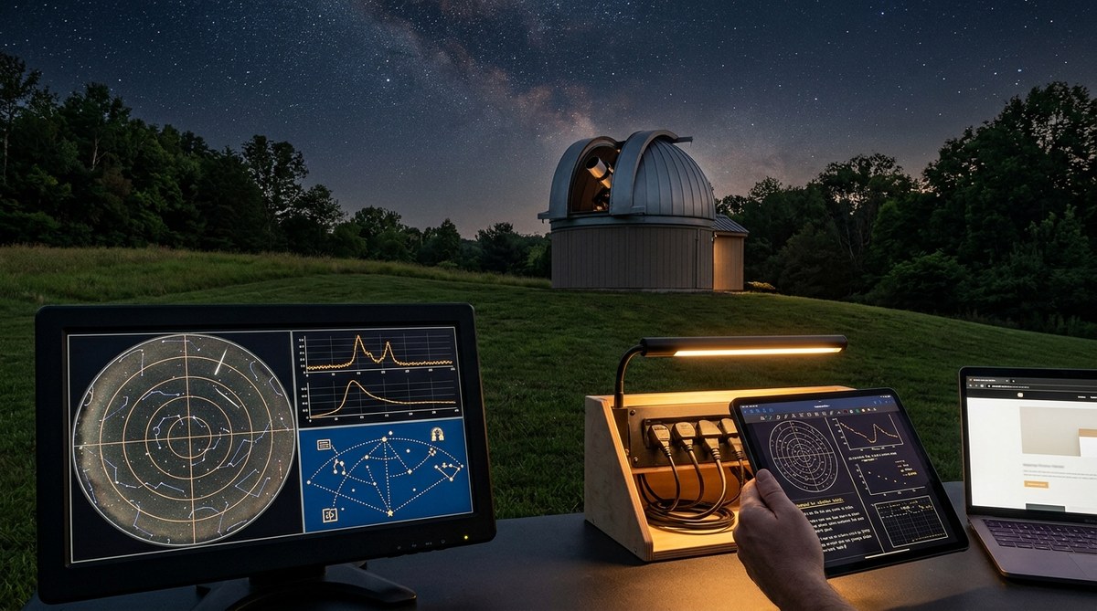
Decoding Celestial Phenomena: How Remote Observatory Data Reveals the Mysteries of the Night Sky
Watching the night sky has fascinated humanity for centuries. Today, advanced remote observatories provide unprecedented…
DIY Projects
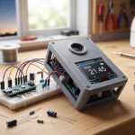
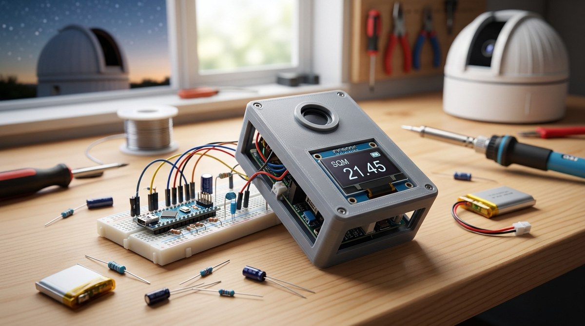
DIY Guide to Building a Portable Sky Quality Meter for Remote Observatories
Building a reliable sky quality measurement device can significantly improve your remote observatory’s performance. Whether…

Software & Automation
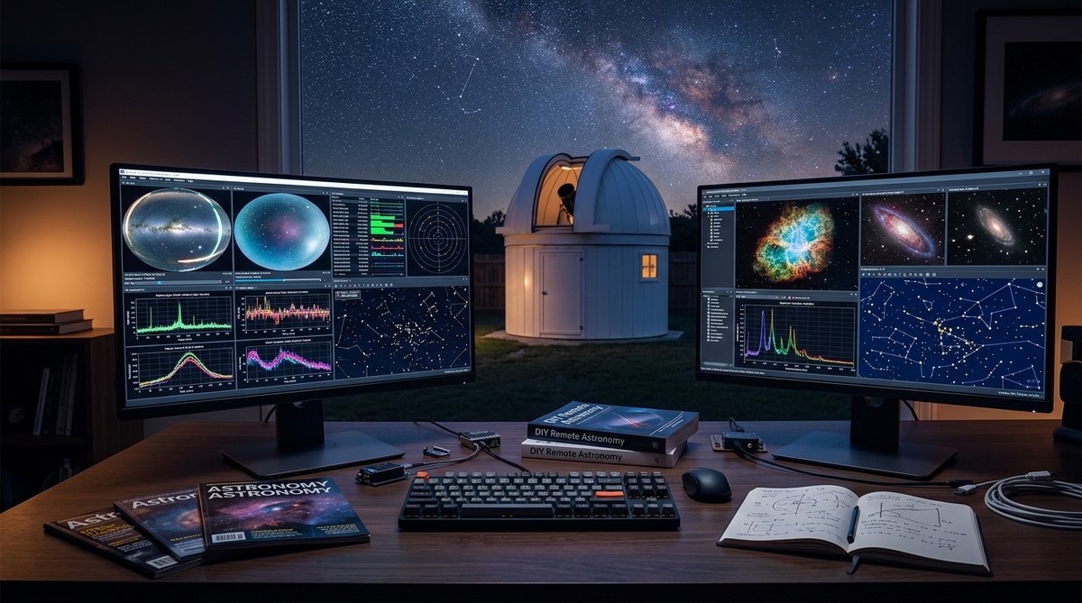
Streamline Your Remote Astronomy Setup with AI-Powered Automation Tools
Getting your telescope to work smoothly from a remote location can feel overwhelming. Juggling hardware,…
Equipment & Setup
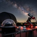
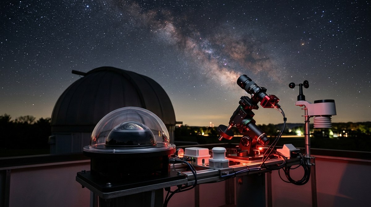
Choosing the Best Equipment for Remote Sky Monitoring to Enhance Your Astronomy Experience
Getting started with remote sky monitoring opens up a world of possibilities for amateur astronomers…
Astrology
Understanding the Impact of Retrograde Motion on Astrology Readings
Retrograde motion is one of the most talked about phenomena in astrology. When you see…
Observations
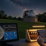
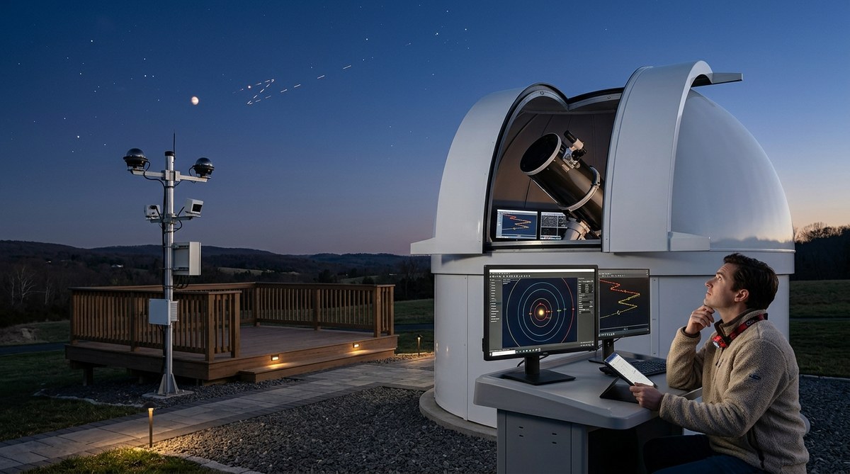
Discover How to Interpret Celestial Events Using Remote Observatory Data
Interpreting celestial events can seem complex, especially when you're relying on remote observatory data. Yet,…

Resource
Educational YouTube Channels That Actually Help You Build Better Observatory Systems
Building and maintaining a quality observatory system can seem complex, especially for those new to…
Resource
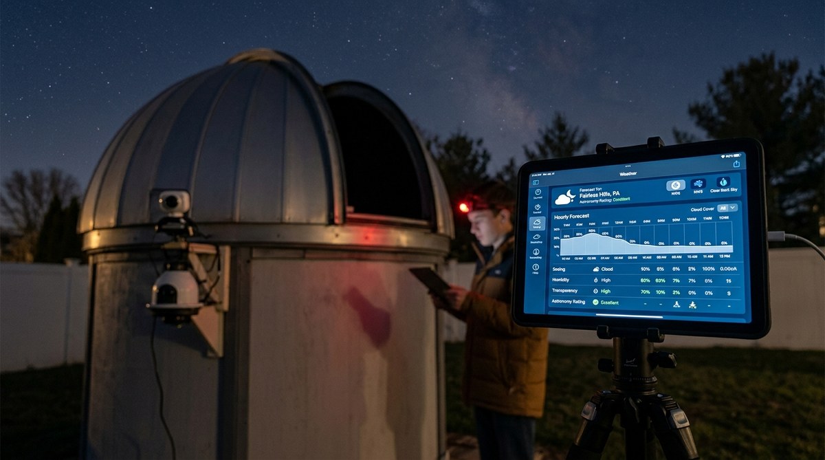
Where to Find Reliable Weather Data for Astronomy Observation Planning
Planning an astronomy session hinges on more than just knowing the night sky. It requires…
Guides & Tutorials
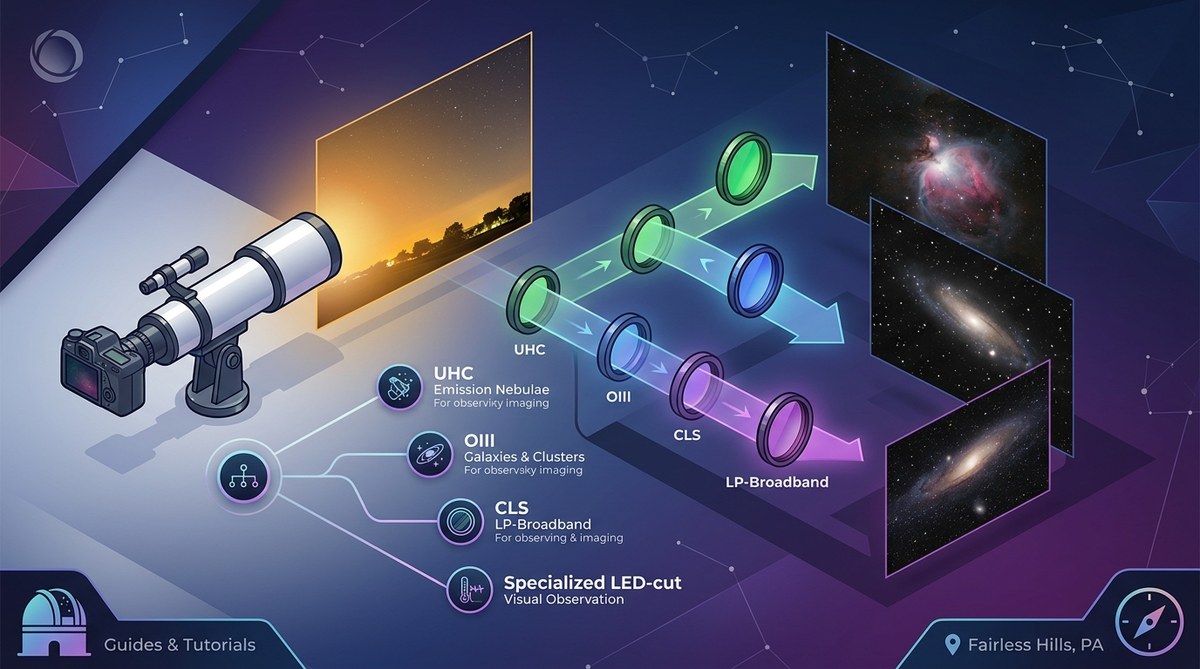
What Light Pollution Filter Should You Actually Use? A Decision Framework
Amateur astrophotographers and stargazing enthusiasts often face a common challenge: how to capture clear images…